
1. An overview of the
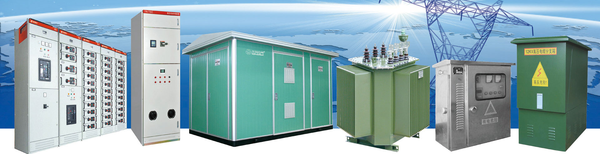
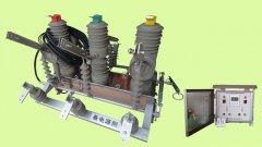
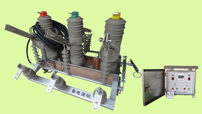
ZYKCQ - 70 type high pressure double power supply for each device (hereinafter referred to as device) is composed of a high voltage vacuum circuit breaker and intelligent controller of two parts.Applied to ac 50 hz, rated voltage of 12 kv, rated current 630 a dual power supply system, when the power failure or undervoltage occurred in power source automatic switch all the way to the other along the normal power supply, reliable guarantee for the continuity of power supply.At the same time many advantages such as short circuit and over current protection interlock function, effectively avoid the unnecessary power supply shock again when load failure.In the event of blackouts during the common power supply fails, switch device can complete with standby power automatic switch, to ensure the reliability and security.Also can according to the needs of the load for the switching between the two power supplies.Particularly applicable to not allow the important place of power, as an important electrical control device to ensure continuous power supply.As a new generation of novel design, perfect in performance, safe and reliable, high degree of automation, wide scope of use of the compound type dual power automatic switch products.Products are designed to ensure that the two way high voltage power supply is completely isolated, at the same time, the perfect and reliable mechanical and electrical chain, so it is of very high safety and reliability.The product is suitable for higher requirements for power supply reliability and safety of double power supply electric power users, as a dual power supply system of control and protection Settings.
Products are widely used in oil field, mine, metallurgy, chemical industry, railways, communications, machinery and so on 10 kv distribution line, industrial and mining enterprises, 10 kv line.
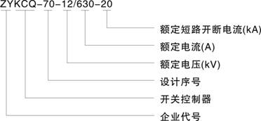
2. The model and its meaning
3. The accord with a standard
3.1 the general IEC 60947-1
IEC 60947-6-3.2 1 (1989) < < automatic switch electrical > >
3.3 GB 14048.11
IEC 60947-2-3.4 GB14048.2 < < breaker > >
4. The normal working conditions
4.1 ambient air temperature limit shall not exceed + 55 ��, lower limit not more than 25 ��.
4.2 installation height less than 2000 meters above sea level.
4.3 relative humidity of the atmosphere in the ambient air temperature is + 40 �� when not more than 50%, at low temperature can have higher humidity;The wettest month
Monthly average minimum temperature of + 25 ��, the average relative humidity is 90%, the biggest change because of the humidity and considering the happened in the condensation on the surface of the product.
4.4 pollution levels for level 3.
4.5 run where no strong vibration and impact, no corrosive action on metals, and damage the insulation of harmful gases, no serious dust, no conductive particles and explosion dangerous substances.
5. The main technical parameters
|
project |
unit |
parameter |
||||
|
The rated voltage |
kV |
12 |
||||
|
Rated current |
A |
630 |
||||
|
The rated short circuit breaking current |
kA |
20 |
||||
|
The rated short circuit close current (peak value) |
50 |
|||||
|
Rated current peak tolerance |
50 |
|||||
|
Rated short-time resistance current |
20 |
|||||
|
The rated short circuit duration |
S |
4 |
||||
|
The rated insulation level |
Lightning shock compression (peak value) |
kV |
75 |
|||
|
1 min power frequency withstand voltage |
Do try |
42 |
||||
|
Try the wet |
34 |
|||||
|
The rated operating sequence |
|
Points - 0.3 - s - s - 180 points |
||||
|
The rated short circuit current open circuit |
time |
30 |
||||
|
Mechanical life |
10000 |
|||||
|
The rated operating voltage (points coil) |
V |
DC220��110��AC220 |
||||
|
Dynamic and static contact allowed to wear the accumulative thickness |
mm |
3 |
||||
|
Overcurrent trip rated current |
A |
5 |
||||
|
Ct (current transformer) current ratio |
|
200/5 400/5 400/5 |
||||
|
Contact from |
mm |
9 + 1 |
||||
|
Contact distance |
3 + 1 |
|||||
|
The average brake speed |
m/s |
1.0 + / - 0.3 |
||||
|
The average closing speed |
1.0 + / - 0.25 |
|||||
|
Break-brake time (shunt trip) |
The highest rated operating voltage |
ms |
�Q 60 |
|||
|
The minimum operating voltage |
�Q 100 |
|||||
|
Closing time |
�Q 100 |
|||||
|
Closing bounce time |
�Q 2 |
|||||
|
Three phase points closing synchronism |
�Q 2 |
|||||
|
Each phase loop dc resistance |
Mu omega. |
�Q 200 |
||||
|
Energy storage motor |
The rated voltage |
V |
- 220. |
|||
|
Rated power |
W |
70 |
||||
|
Energy storage time |
S |
�Q 10 |
||||
|
The weight of the |
kg |
210 |
||||
7. Intelligent controller
7.1 the controller main technical parameters:
7.1.1 rated voltage: AC220V allowable deviation - 15% ~ + 10%;
7.1.2: rated frequency 50 hz allowable deviation - 5% ~ + 5%;
7.1.3 waveform distortion < 10%
7.1.4 mechanical life: (N - R - N cycle) for 10000 times
7.1.5 flow adjustable range: 3-6 a
7.1.6 quick break adjustable scope: three times, four times, five times, six times
7.2 product features
7.2.1 equipped with LCD display, fault alarm;
7.2.2 strong anti-jamming capability, high precision;
7.2.3 complete protection function;
7.2.4 start automatically reciprocating switching;
7.2.5 switch time delay is adjustable, action time and accurate;
7.2.6 manual automatic and wireless remote control points, closing function;
7.2.7 flow prevention, over-current, small volume, high breaking, compact structure, beautiful appearance;
7.2.8 anti-corrosion performance is good, reliable power supply;
7.2.9 noise-free operation, energy conservation and low consumption, installation convenient and simple operation, stable performance.
8. Debugging and installation
8.1 debugging
*Before installation please click the following method for debugging, commissioning normal rear can put into use.
8.1.1Master for each drop test
8.1.1.1 press the logo, on the controller to form a complete set of corresponding air on cable and device of high voltage vacuum circuit breaker socket installation, tighten.
8.1.1.2 to the master, for power supply.
8.1.1.3 open two power switch of the controller, the product into the working state.The electric power supply, often if common power supply back knife switches in the closing position, the time delay device of high voltage vacuum circuit breaker closing transmission after 5 seconds;If a common power supply in standby power breaker back shots back switching states or other states, first make brake device of high voltage vacuum circuit breaker points, has confirmed that it is in a state of break-brake, after a delay on commonly used power shots back knife switches, again in the case of confirmed breaker has been in place, then delay after 5 seconds to device of high voltage vacuum circuit breaker closing.Closed electric switch, controller to detect common power loss, after the above processing steps, first make brake device of high voltage vacuum circuit breaker points, and then cast in standby power cast back knife switches, to make the device of high voltage vacuum circuit breaker switching power, to complete a conversion process (often electricity - for electricity).Again open the electric switch, controller to detect common power supply, automatic make brake device of high voltage vacuum circuit breaker points, breaker commonly used power shots back again, and then make the device of high voltage vacuum circuit breaker closing, to complete a conversion process (for electricity - often electricity).
8.1.2Over-current protection
This product factory set data flow for current transformer secondary side 5 a, quick break for 15 a secondary side, according to the user's need to make changes.Through raising the inverter for high voltage vacuum circuit breaker with large current, make the secondary side current is greater than 5 a, conversion device due to flow will be closing atresia treated the breaker closing work in current device of high voltage vacuum circuit breaker, two power supplies are not automatic conversion.Unlock method for manual press the corresponding closing unlock button on the panel, or by remote control by remote control switch to unlock.
8.1.3Remote debugging
8.1.3.1 remote control points, closing operation: the dual power switch device is equipped with remote control, wireless remote control points, closing operation can be:
Break-brake 8.1.3.2 remote control operation: continue to push the "lock" button on the remote control more than 2 seconds to break-brake operations, plant will be closing closure treatment at the same time.
8.1.3.3 remote closing operation: continue to push the "lock" button on the remote control for closing the unlock operation for more than 2 seconds.
8.1.4Set the LCD display
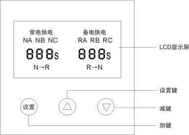
8.1.4.1 panel use high-grade green backlit LCD display in Chinese large screen display working status, normal operation of the open weak backlighting to facilitate observation in any environment.After the long press "set" key for 2 seconds, the controller into the Settings menu tree, at the same time strong backlight light in order to clear view and modify the parameters.
8.1.4.2 display on the LCD display common power supply (NA, NB, NC), standby power (RA, RB, RC), all the way when any uneven power supply power failure, the power supply corresponds to the letter.When any power failure happened all the way to cut off the power supply and issue a report to the police.
8.1.4.3 controller parameter Settings
Example: the original set as factory default, now changed to N - > R time 20 s, R - N time for 5 s
A. enter the parameter setting mode
In normal display mode, long press "set" key for 2 seconds and then released, the controller will enter the parameter setting mode, strong backlighting lighting at the same time, the LCD will display the set time N - R interface.

B. changes commonly used power transfer to standby power delay time
LCD display N - R time, through the panel on the "key", "reduction" of time step increase, decreases.If long press "add", "key reduction" super 2 seconds will enter a rapid mode, increase and decrease the time value will be quick to add and subtract operations, release the button to stop.Users can cooperate treatment in accordance with the specific circumstances, to quickly and accurately set the parameter values.

C. changes standby power conversion to standby power delay time
Continue to short press "set" key, the LCD screen display R - N time, through panel "with key" and "reduction" of time step increase, decreases.If long press "add", "key reduction" super 2 seconds will enter a rapid mode, increase and decrease the time value will be quick to add and subtract operations, release the button to stop.Users can cooperate treatment in accordance with the specific circumstances, to quickly and accurately set the parameter values.

D to change the dual alarm mode
Continue to short press "set" key, the LCD screen display way of BJ, through panel "with key" "minus key" alarm way step change."ON "said the police open," OFF "said the police shut down.

E exit parameters setting mode
Continue to short press "set" key, the above steps 2 ~ 4 automatic controller will cycle.If set to complete want to exit the parameter setting mode, please long press "set" key for 3 seconds to exit parameters setting mode, return to normal display.If they do not press any key and wait for 20 seconds automatic controller can automatically exit parameters setting mode, return to the normal display interface.

Note: in the process of setting, such as do not need to modify the parameters, direct short press "set" key to enter the next item parameter Settings.On to the next parameter is set at the same time, a modified content parameters on the fast preservation. The user does not have to show each loop wheel, modify the finish can be according to the above step 5 operating mode exit parameters setting mode, please check it again after the set to complete.
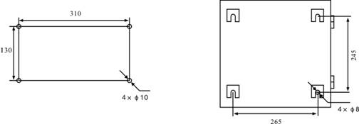
9 installation
Figure 9.1 for each device appearance and installation size

Figure 9.2 intelligent controller installation size
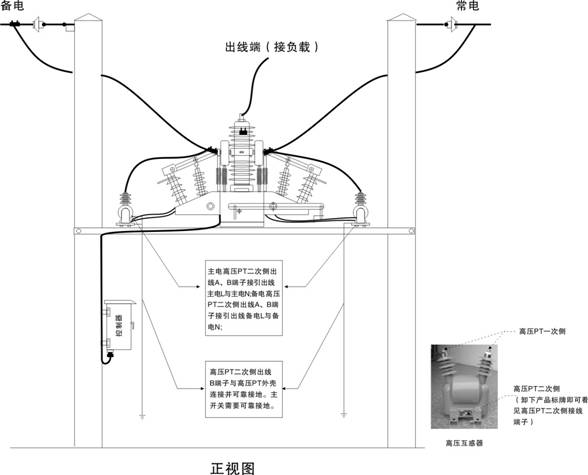
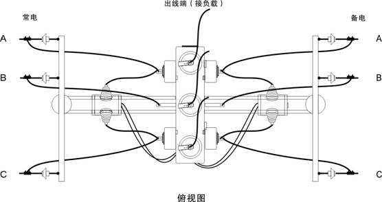
Note: dual power supply for each unit and high pressure PT when installation, please press the high voltage safety insulation distance isolation installation.Cable used in high voltage side must adopt corresponding voltage grade high voltage cable, and follow the relevant safety insulation distance line.All equipment must be safe and reliable grounding.Low voltage side cable should also pay attention to safety wiring insulation distance.
9.3 installation method
10. Failure analysis and elimination
10.1 the situation of the work on the open intelligent controller panel after master the electricity, the electric power switch, panel status to the supply switching lights all the way, the other points all the way brake lights, or both road show the brake light is lit.The LCD panel is displayed according to the pattern shown in this manual 8.1.4.
10.2 when the intelligent controller work, if you hear a voice squeaky relay jitter inside, please close the master electrical and intelligent controller on the front panel electric power switch, check whether the power supply voltage is too low, and start to restore normal voltage controller.
10.3 after Lord for electric power automatic control device not conversion, please check the intelligent controller panel left and right sides of the main power and electric power switch is on.Controller and whether institutions corresponding air plug screw tightly, at the same time observe the controller panel LCD display on the main power, whether for electric undervoltage (phase).
10.4 after automatic conversion switch institutions and points, please manual inspection agencies is closing in place.
10.5 such as remote control remote control no response, please check whether the remote control right of form a complete set (the number on the reverse of the remote control should be consistent with the body on the remote control code), remote control electric, operation specification, the controller outside antenna is normal, whether there is a strong electromagnetic interference in the environment.
10.6 flow regulating current too high or too low, please test the transformer and the heat flow device whether formal whether accurate.
Note: when the power switch overload or manual brake, you must manually switching (also known as unlock) cannot normal transformation.When debugging when the main electricity have electric power, main electricity not switching to use manual switching.When the main electric power for electric also want to use manual switching to unlock, without closing this debugging to normal before normal put into use.
 Mobile
 WeChat
 Eqxiu Show