1. An overview of the
With the development of the society, people has higher requirement on the power supply reliability.Many occasions to ensure the reliability of power supply with two way power supply, which requires a product in reliable switching between two power supplies, the company produced ZYKCQ - 50 double power automatic switching device is designed in order to meet the demand of this kind of development.
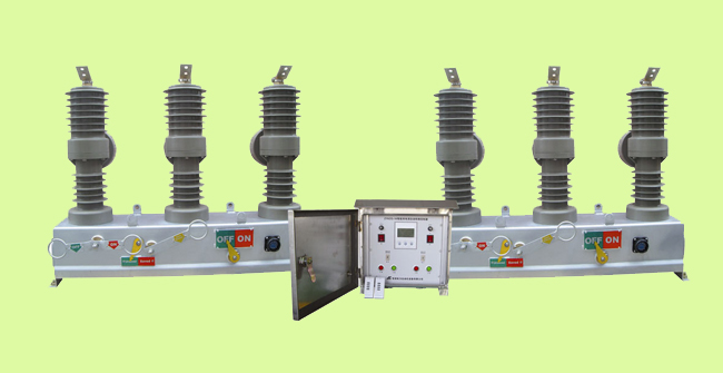
ZYKCQ - 50 double power automatic switching device consists of two high voltage vacuum circuit breaker and intelligent controller of two parts.Applied to the communication12 kv 50 hz, rated voltage, rated current 1250 a dual power supply system, when the power failure or undervoltage occurred in power source automatic switch all the way to the other along the normal power supply, reliable guarantee for the continuity of power supply.At the same time many advantages such as short circuit and over current protection interlock function, effectively avoid the unnecessary power supply shock again when load failure.In common power failure occurs, switching device can complete with standby power automatic switch, to ensure the reliability and security.Also can according to the needs of the load for the switching between the two power supplies.Particularly applicable to not allow the important place of power, as an important electrical control device to ensure continuous power supply, is with high voltage vacuum circuit breaker of the replica dual power automatic switch device.As a new generation of novel design, perfect in performance, safe and reliable, high degree of automation, wide using range of dual power automatic switch products.
Products are widely used inOil fields, mines, 10 kv distribution line, industrial and mining enterprises, 10 kv line.
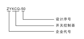
2. The product model and meaning
3. The accord with a standard
3.1 the general IEC 60947-1
IEC 60947-6-3.2 1 (1989) < < automatic switch electrical > >
3.3 GB 14048.11
IEC 60947-2-3.4 GB14048.2 < < breaker > >
4. The normal working conditions
4.1 ambient air temperature limit shall not exceed + 40 ��, lower limit not more than 25 ��, the average temperature values are not more than 24 hours + 35 ��.
4.2 installation height less than 2000 meters above sea level.
4.3 relative humidity of the atmosphere in the ambient air temperature is + 40 �� when not more than 50%, at low temperature can have higher humidity;The wet month month average minimum temperature of 25 ��, the average maximum relative humidity is 90%, and considering the due to humidity changes occur in the condensation on the surface of the product.
4.4 pollution levels for level 3.
4.5 run where no strong vibration and impact, no corrosive action on metals, and damage the insulation of harmful gases, no serious dust, no conductive particles and explosion dangerous substances.
5. The main technical parameters
|
project
|
unit
|
parameter
|
|
The rated voltage
|
kV
|
12
|
|
Rated current
|
A
|
In 630,1250
|
|
The rated short circuit breaking current
|
kA
|
20
|
|
The rated short circuit close current (peak value)
|
50
|
|
Rated current peak tolerance
|
50
|
|
Rated short-time resistance current
|
20
|
|
The rated short circuit duration
|
S
|
4
|
|
The rated insulation level
|
Lightning shock compression (peak value)
|
kV
|
And, over the ground75, 85 fracture
|
|
1 min power frequency withstand voltage
|
And, over the ground42, fracture 48
|
|
The rated operating sequence
|
|
points- 0.3-180 - s - s - close points or points (electric)
|
|
The rated short circuit current open circuit
|
time
|
30
|
|
Mechanical life
|
10000
|
|
The rated operating voltage (points coil)
|
V
|
DC220��110��AC220
|
|
Dynamic and static contact allowed to wear the accumulative thickness
|
mm
|
3
|
|
Overcurrent trip rated current
|
A
|
5
|
|
Ct (current transformer) current ratio
|
|
200/5 400/5 400/5,1250/5
|
|
Contact from
|
mm
|
9 + 1
|
|
Contact distance
|
2
|
|
The average brake speed
|
m/s
|
1.2 + / - 0.2
|
|
The average closing speed
|
0.6 + / - 0.2
|
|
Break-brake time
|
ms
|
15 -50
|
|
Closing time
|
25 ~80
|
|
Closing bounce time
|
�Q 2
|
|
Three phase points closing synchronism
|
�Q 2
|
|
Each phase loop dc resistance
|
Mu omega.
|
�Q 80
|
|
Energy storage motor
|
The rated voltage
|
V
|
- 220.
|
|
Rated power
|
W
|
70
|
|
Energy storage time
|
S
|
�Q 8
|
|
The quality of
|
kg
|
85
|
6. Intelligent controller
6.1 the controller main technical parameters:
6.1.1Rated voltage: AC220V allowable deviation - 15% ~ + 10%;
6.1.2: rated frequency 50 hz allowable deviation - 5% ~ + 5%;
Also 6.1.3Waveform distortion is < 10%
6.1.4Mechanical life: (N - R - N cycle) for 10000 times
6.1.5Flow adjustable range: 3-6 a
6.1.6Quick break adjustable scope: three times, four times, five times, six times
6.2 product features
6.2.1Equipped with LCD display, fault alarm;
6.2.2Strong anti-jamming capability, high precision;
6.2.3Complete protection function;
6.2.4Start automatically reciprocating switching;
6.2.5The action time of the switch time delay is adjustable, accurate;
6.2.6Manual automatic and close function and the wireless remote control;
6.2.7Against the flow, flow, small volume, high breaking, compact structure, beautiful appearance;
6.2.8Anti-corrosion performance is good, reliable power supply;
6.2.9No noise, energy conservation and low consumption, convenient installation simple operation, high stability.
6.2.10This device of its control functions see the table below: in the condition of automatic control, power supply by the common normal of switching power supply, when the common power supply is abnormal, after a certain time delay automatically switch to the standby power supply;After the common power supply returns to normal, after a certain time delay to return to the common power supply automatically.
Switching action delay (1-999 - s, the user has no special requirements when the factory setting in 10 s, if you have any other special requirements, please specify when the customer ordering).
Return to action delay (1-999 - s, the user has no special requirements when the factory setting in 10 s, if you have any other special requirements, please specify when the customer ordering).
7. Debugging and installation
7.1 debugging
* Before installation please click the following method for debugging, commissioning normal rear can put into use.
7.1.1 Lord for electric automatic conversion debugging
8.1.1. 1 press the logo, on the controller to form a complete set of two cables and high voltage vacuum circuit breaker tighten-up, corresponding to the air outlet.
8.1.12 to the master, for power supply.
8.1.1. 3 open two power switch of the controller, the product into the working state.The main electric power supply, if the primary electrical high voltage vacuum circuit breaker is in a state of breaking past the main electrical delay closing time main power switch.If no action may be blocking, please manually press the main power switch button to manually switch is unlocked.Shut down the main electricity, main electric controller should lose the main electric brake high voltage vacuum circuit breaker points.After a delay closing time for electricity for electric high voltage vacuum circuit breaker closing, for electrical work.Master to complete an automatic conversion process ().Give the main electric power, master electricity to make controller should be detected electric high voltage vacuum circuit breaker breaking, the main electrical high voltage vacuum circuit breaker through the main electrical switching delay closing time, the main electrical work.Complete an automatic conversion process (to master).
7.1.2 Over-current protection
This product factory set data flow for current transformer secondary side 5 a, quick break for 15 a secondary side, according to the user's need to make changes.Through raising the inverter for high voltage vacuum circuit breaker with large current, make the secondary side current is greater than 5 a, conversion device will be closing due to over current atresia handle breaking current switching work vacuum switch, two power supplies are not automatic switching.Unlock method for manual press the corresponding closing unlock button on the panel, or by remote control to master, and the corresponding electric remote control switch to unlock.
7.1.3 Remote debugging.
7.1.3. 1 remote control points, closing operation: master, this device corresponding to the two power supplies are equipped with remote control, wireless remote control points, closing operation can be:
7.1.3Break-brake operations: 2 remote control button on the remote control in turn. A, B, C button of break-brake operations, at the same time, the device will be closing closure treatment.
7.1.33 remote closing operation: in turn button on the remote control D, C, B button for closing the unlock operation.
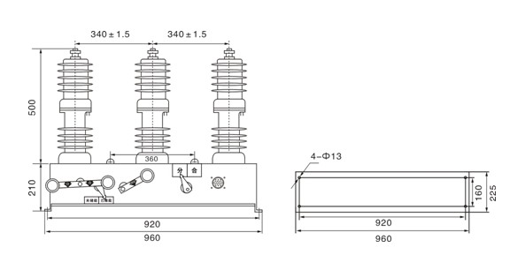
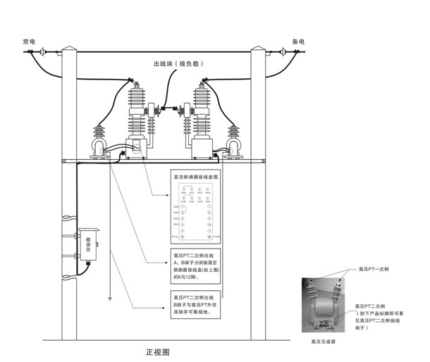
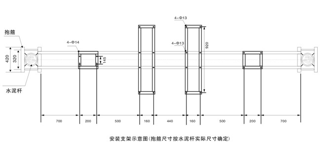
Installed 8.
Figure 8.1 appearance and installation size
Figure 8. 2 intelligent controller installation size
8.3 installation method
Note: high voltage circuit breaker and high-voltage PT when installation, please press the high voltage safety insulation distance isolation installation.Cable used in high voltage side must adopt corresponding voltage grade high voltage cable, and follow the relevant safety insulation distance line.All equipment must be safe and reliable grounding.Low voltage side cable should also pay attention to safety wiring insulation distance.


 Mobile
 WeChat
 Eqxiu Show